Hardware Assembly and Mounting
This guide covers the physical assembly of the Mini Pupper v2, including mounting the camera, cooling fan, and 3D printed components.
Prerequisites
Before starting, ensure you have:
- Completed Cable Preparation
- Mini Pupper v2 robot (assembled base)
- 3D printed camera mount
- 3D printed fan mount
- M2 and M2.5 screws
- Small Phillips screwdriver
Part 1: Camera Mount Installation
Step 1: Prepare the Camera Mount
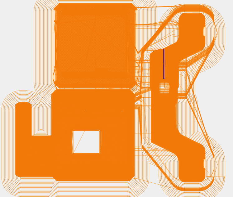
3D Printed Camera Mount:
- Download from camera.zip
- Print with PLA or PETG
- 20-30% infill recommended
- Enable supports if needed
Step 2: Attach Camera to Mount
- Position the camera module in the mount bracket
- Camera lens should face forward
- PCB sits in the bracket recess
- Adjust camera angle
- Typical angle: 10-15° downward
- Allows robot to see ground and forward
- Test angle before securing
- Secure the camera
- Use M2 screws (usually 2-4 screws)
- Don’t overtighten - plastic can crack
- Camera should be stable but not stressed
Step 3: Mount Bracket to Robot Head
- Position the mount on the Mini Pupper’s head
- Align with mounting holes
- Ensure ribbon cable has clearance
- Insert screws (M2 or M2.5)
- Start all screws before tightening
- Tighten in a cross pattern
- Alternate between screws for even pressure
- Verify stability
- Mount should be solid with no wobble
- Camera should maintain angle
- Ribbon cable should have slack
Step 4: Test Head Movement
Important: Test before final assembly
- Manually move the head through full range of motion
- Pan left and right
- Tilt up and down
- Check for cable interference
- Check for issues
- Ribbon cable should move freely
- No pinching or snagging
- No tension on cable connections
- Adjust cable routing if needed
- Add slack where necessary
- Secure with tape or small zip ties
- Ensure clearance from servos
Part 2: Cooling Fan Installation
Step 1: Prepare the Fan Mount
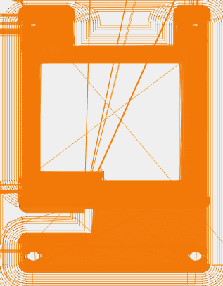
3D Printed Fan Mount:
- Download from fan.zip
- Print with PLA or PETG
- 20-30% infill recommended
- Check fit before final assembly
Step 2: Install Fan in Mount
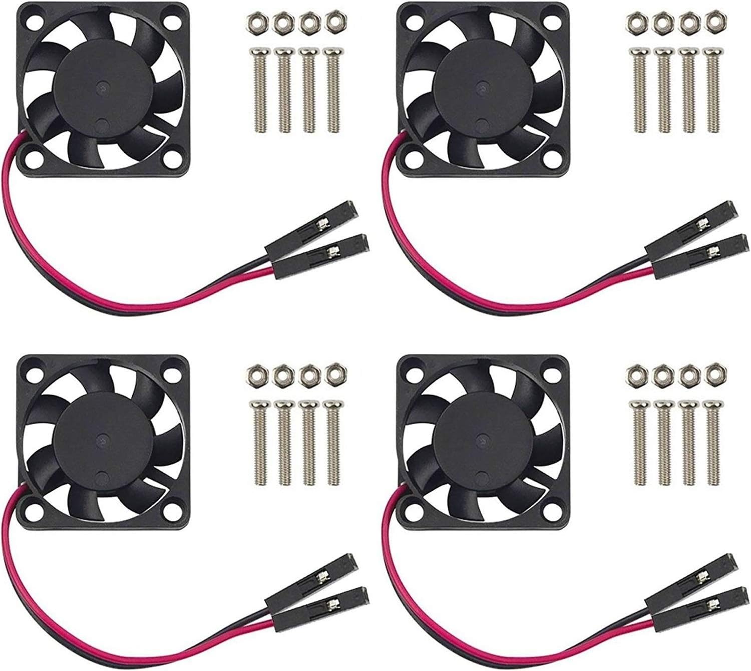
- Check airflow direction
- Fan should blow air ONTO the Raspberry Pi
- Look for arrow on fan housing
- Arrow shows airflow direction
- Position fan in mount
- Align screw holes
- Ensure wires exit in correct direction
- Secure with screws
- Use screws included with fan (usually M3)
- Tighten evenly
- Don’t overtighten plastic
Step 3: Mount Fan Assembly to Robot
- Position the fan mount on the robot body
- Should be above or near the Raspberry Pi
- Ensure airflow path is clear
- Check wire routing to GPIO pins
- Attach to mounting points
- Use M2.5 or M3 screws
- Secure firmly but don’t crack plastic
- Verify airflow
- No obstructions in front of fan
- Air can flow freely over Raspberry Pi
- Wires don’t block airflow
Part 3: Cable Management
Organize and Secure Cables
Goals:
- Prevent snagging on moving parts
- Maintain neat appearance
- Allow for disassembly if needed
- Ensure reliability
Techniques:
- Bundle related cables
- Use small zip ties or twist ties
- Don’t overtighten - allow some movement
- Group by function (power, data, etc.)
- Route along structural members
- Follow robot frame when possible
- Use existing cable channels
- Avoid crossing open spaces
- Secure at stress points
- Near connectors
- At movement joints
- Where cables change direction
- Leave service loops
- Extra length near moving parts
- Allows for maintenance
- Prevents tension on connectors
Cable Routing Best Practices
Camera Ribbon Cable:
- Gentle curves only (no sharp bends)
- 2-3cm slack near head joint
- Secured to prevent flopping
- Away from servo mechanisms
Fan Wires:
- Short, direct path to GPIO
- Secured to prevent disconnection
- Not blocking airflow
- Protected from pinching
USB Cables (if used):
- Route to accessible location
- Secure to prevent pulling
- Label for identification
Part 4: Final Assembly Check
Visual Inspection
Check each component:
- Camera mounted securely
- Camera angle appropriate (10-15° down)
- Camera ribbon cable has slack
- Fan mounted securely
- Fan airflow direction correct
- Fan wires connected to GPIO (Pin 4 & 6)
- All cables routed neatly
- No cables near moving parts
- All screws tightened (but not overtightened)
- No loose parts or tools left inside
Functional Tests
Before closing up:
- Power on test
- Connect power adapter
- Verify power LED
- Check fan spins
- Wait for boot sequence
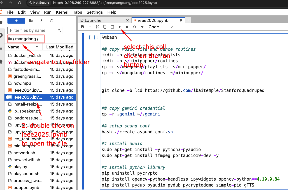
- Camera test
# SSH into Mini Pupper ssh ubuntu@<mini-pupper-ip> # List cameras libcamera-hello --list-cameras # Should show: Available cameras: 1 - Movement test
- Robot should stand up after boot
- Manually test head movement
- Check for cable interference
- Listen for unusual servo sounds
- Temperature test
# Check CPU temperature
vcgencmd measure_temp

# Should be under 60°C at idle
# Fan should keep it under 70°C under load
Part 5: Troubleshooting Assembly Issues
Camera Mount Issues
| Problem | Cause | Solution |
|---|---|---|
| Mount wobbles | Screws not tight | Tighten screws evenly |
| Camera angle changes | Mount flexing | Use more screws, reinforce mount |
| Ribbon cable pinched | Poor routing | Reroute with more slack |
| Mount cracked | Overtightened | Print new mount, use less force |
Fan Mount Issues
| Problem | Cause | Solution |
|---|---|---|
| Fan vibrates | Loose mounting | Tighten screws, check alignment |
| Fan noisy | Obstruction | Check for debris, ensure clearance |
| Poor cooling | Wrong airflow direction | Reverse fan orientation |
| Mount loose | Wrong screws | Use correct size screws |
Cable Management Issues
| Problem | Cause | Solution |
|---|---|---|
| Cables snagging | Poor routing | Reroute away from moving parts |
| Ribbon cable damaged | Sharp bend | Replace cable, improve routing |
| Wires disconnecting | No strain relief | Add zip ties near connectors |
| Messy appearance | No organization | Bundle and secure cables |
Part 6: Maintenance Tips
Regular Checks (Monthly)
- Inspect camera mount
- Check for cracks or loosening
- Verify camera angle hasn’t shifted
- Clean lens with microfiber cloth
- Check fan operation
- Listen for unusual noises
- Verify fan spins freely
- Clean dust from fan blades
- Inspect cables
- Look for wear or damage
- Check connections are secure
- Verify routing hasn’t shifted
- Tighten screws
- Vibration can loosen screws over time
- Check all mounting screws
- Don’t overtighten
Cleaning
Camera Lens:
- Use microfiber cloth only
- Gentle circular motion
- Don’t use liquids unless necessary
- Compressed air for dust
Fan:
- Power off first
- Use compressed air
- Don’t spin fan manually
- Check for obstructions
Cables:
- Wipe with dry cloth
- Check for fraying
- Don’t pull or tug
- Replace if damaged
Part 7: Upgrades and Modifications
Optional Enhancements
Better Camera Mount:
- Design with adjustable angle
- Add vibration dampening
- Include cable management clips
Improved Cooling:
- Add heatsinks to Raspberry Pi
- Use larger fan (40mm)
- Add temperature-controlled fan speed
Cable Management:
- 3D print cable clips
- Use spiral cable wrap
- Add cable channels to body
Protection:
- Add camera lens protector
- Use dust covers
- Protect exposed connectors
Safety Notes
During Assembly:
- Work on stable, flat surface
- Keep small parts organized
- Don’t force components
- Use correct size screwdriver
Electrical Safety:
- Power off before working on robot
- Don’t touch GPIO pins while powered
- Verify connections before powering on
- Keep liquids away from electronics
Mechanical Safety:
- Watch for pinch points
- Keep fingers clear of servos
- Don’t overtighten screws on plastic
- Wear safety glasses when using compressed air
Next Steps
After completing hardware assembly:
- Setup Mini Pupper - Configure software and WiFi
- Jupyter Setup - Access the web interface
- Test Camera - Verify camera functionality
- Test Sensors - Check all hardware