Lab 7A/7B: Rotary Encoder (Week 11-12)
Overview
In this lab, you will interface with a rotary encoder - a common input device that converts rotational motion into digital signals. You will design a state machine to decode the rotation direction and create an up/down counter controlled by the encoder.
Learning Objectives
After completing this lab, you will be able to:
- Understand rotary encoder operation (quadrature encoding)
- Implement debouncing for mechanical switches
- Design a Finite State Machine (FSM) to decode rotation
- Create an up/down counter controlled by the encoder
- Apply state machines to real-world interfacing problems
Background: Rotary Encoder
What is a Rotary Encoder?
A rotary encoder is an electro-mechanical device that converts angular position or rotation to digital signals. It outputs two square waves (A and B) that are 90° out of phase (quadrature signals).
Quadrature Encoding
The phase relationship between signals A and B indicates rotation direction:
Clockwise Rotation:
    A: ─┐ ┌─┐ ┌─┐ ┌─
       └─┘ └─┘ └─┘
    B: ──┐ ┌─┐ ┌─┐ ┌
        └─┘ └─┘ └─┘
    (A leads B by 90°)

Counter-Clockwise:
    A: ──┐ ┌─┐ ┌─┐ ┌
        └─┘ └─┘ └─┘
    B: ─┐ ┌─┐ ┌─┐ ┌─
       └─┘ └─┘ └─┘
    (B leads A by 90°)
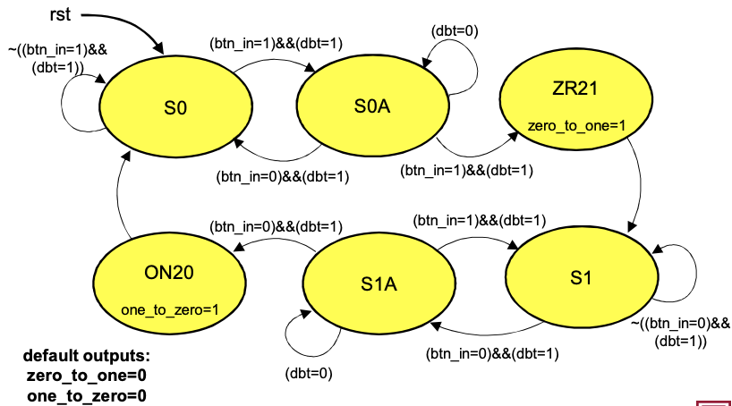
Figure 1: Rotary Encoder Quadrature State Machine
State Transitions
| Current State (A,B) | Next State (A,B) | Direction |
|---|---|---|
| 00 → 01 | Clockwise | |
| 01 → 11 | Clockwise | |
| 11 → 10 | Clockwise | |
| 10 → 00 | Clockwise | |
| 00 → 10 | Counter-Clockwise | |
| 10 → 11 | Counter-Clockwise | |
| 11 → 01 | Counter-Clockwise | |
| 01 → 00 | Counter-Clockwise |
Design: Debouncing
Why Debounce?
Mechanical contacts in encoders cause contact bounce - rapid oscillations between 0 and 1 when the contact changes state. This can cause false state transitions.
Debounce Circuit
module debounce #(
    parameter DEBOUNCE_TIME = 50000  // Clock cycles (~1ms at 50MHz)
)(
    input  logic clk,
    input  logic rst_n,
    input  logic noisy,      // Raw input from encoder
    output logic clean       // Debounced output
);

    logic [15:0] counter;
    logic        sync_in, prev_in;

    // Synchronizer (2-stage for metastability)
    always_ff @(posedge clk or negedge rst_n) begin
        if (!rst_n) begin
            sync_in <= 1'b0;
            prev_in <= 1'b0;
        end else begin
            sync_in <= noisy;
            prev_in <= sync_in;
        end
    end

    // Debounce counter
    always_ff @(posedge clk or negedge rst_n) begin
        if (!rst_n) begin
            counter <= '0;
            clean <= 1'b0;
        end else if (prev_in != clean) begin
            // Input different from stable output
            if (counter == DEBOUNCE_TIME - 1) begin
                clean <= prev_in;
                counter <= '0;
            end else begin
                counter <= counter + 1'b1;
            end
        end else begin
            counter <= '0;
        end
    end

endmodule
Design: Quadrature Decoder FSM
State Machine Approach
module quadrature_decoder (
    input  logic clk,
    input  logic rst_n,
    input  logic a_in,       // Encoder A (debounced)
    input  logic b_in,       // Encoder B (debounced)
    output logic cw_pulse,   // Clockwise rotation pulse
    output logic ccw_pulse   // Counter-clockwise rotation pulse
);

    // State encoding: {prev_a, prev_b}
    logic [1:0] prev_state, curr_state;

    assign curr_state = {a_in, b_in};

    always_ff @(posedge clk or negedge rst_n) begin
        if (!rst_n) begin
            prev_state <= 2'b00;
            cw_pulse   <= 1'b0;
            ccw_pulse  <= 1'b0;
        end else begin
            prev_state <= curr_state;

            // Detect transitions
            case ({prev_state, curr_state})
                // Clockwise: 00→01→11→10→00
                4'b00_01: begin cw_pulse <= 1'b1; ccw_pulse <= 1'b0; end
                4'b01_11: begin cw_pulse <= 1'b1; ccw_pulse <= 1'b0; end
                4'b11_10: begin cw_pulse <= 1'b1; ccw_pulse <= 1'b0; end
                4'b10_00: begin cw_pulse <= 1'b1; ccw_pulse <= 1'b0; end

                // Counter-clockwise: 00→10→11→01→00
                4'b00_10: begin cw_pulse <= 1'b0; ccw_pulse <= 1'b1; end
                4'b10_11: begin cw_pulse <= 1'b0; ccw_pulse <= 1'b1; end
                4'b11_01: begin cw_pulse <= 1'b0; ccw_pulse <= 1'b1; end
                4'b01_00: begin cw_pulse <= 1'b0; ccw_pulse <= 1'b1; end

                default: begin cw_pulse <= 1'b0; ccw_pulse <= 1'b0; end
            endcase
        end
    end

endmodule
Design: Rotation Counter
module rotation_counter #(
    parameter WIDTH = 16
)(
    input  logic                 clk,
    input  logic                 rst_n,
    input  logic                 cw_pulse,    // Clockwise
    input  logic                 ccw_pulse,   // Counter-clockwise
    output logic [WIDTH-1:0]     count
);

    always_ff @(posedge clk or negedge rst_n) begin
        if (!rst_n)
            count <= '0;
        else if (cw_pulse)
            count <= count + 1'b1;
        else if (ccw_pulse)
            count <= count - 1'b1;
    end

endmodule
Complete System Integration
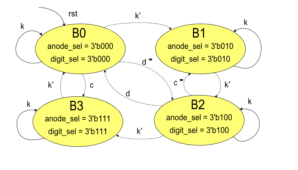
Figure 2: Complete Rotary Encoder System Block Diagram
Top-Level Module
module lab7_top (
    input  logic        MAX10_CLK1_50,
    input  logic [9:0]  SW,
    input  logic [1:0]  KEY,
    input  logic [35:0] GPIO,        // GPIO for encoder
    output logic [9:0]  LEDR,
    output logic [6:0]  HEX0,
    output logic [6:0]  HEX1,
    output logic [6:0]  HEX2,
    output logic [6:0]  HEX3
);

    logic clk, rst_n;
    logic enc_a_raw, enc_b_raw;
    logic enc_a, enc_b;
    logic cw_pulse, ccw_pulse;
    logic [15:0] count;

    assign clk = MAX10_CLK1_50;
    assign rst_n = KEY[0];

    // Encoder inputs from GPIO
    assign enc_a_raw = GPIO[0];
    assign enc_b_raw = GPIO[1];

    // Debounce both encoder signals
    debounce u_deb_a (
        .clk(clk), .rst_n(rst_n),
        .noisy(enc_a_raw), .clean(enc_a)
    );

    debounce u_deb_b (
        .clk(clk), .rst_n(rst_n),
        .noisy(enc_b_raw), .clean(enc_b)
    );

    // Decode quadrature signals
    quadrature_decoder u_decoder (
        .clk(clk), .rst_n(rst_n),
        .a_in(enc_a), .b_in(enc_b),
        .cw_pulse(cw_pulse), .ccw_pulse(ccw_pulse)
    );

    // Up/Down counter
    rotation_counter u_counter (
        .clk(clk), .rst_n(rst_n),
        .cw_pulse(cw_pulse), .ccw_pulse(ccw_pulse),
        .count(count)
    );

    // Display count on 7-segment displays
    svn_seg_decoder u_h0 (.bcd_in(count[3:0]),   .display_on(1'b1), .seg_out(HEX0));
    svn_seg_decoder u_h1 (.bcd_in(count[7:4]),   .display_on(1'b1), .seg_out(HEX1));
    svn_seg_decoder u_h2 (.bcd_in(count[11:8]),  .display_on(1'b1), .seg_out(HEX2));
    svn_seg_decoder u_h3 (.bcd_in(count[15:12]), .display_on(1'b1), .seg_out(HEX3));

    // Show direction on LEDs
    assign LEDR[0] = cw_pulse;
    assign LEDR[1] = ccw_pulse;
    assign LEDR[9:2] = 8'b0;

endmodule
Hardware Connections
Connect the rotary encoder to the DE10-Lite GPIO:
| Encoder Pin | GPIO Pin | Description |
|---|---|---|
| A | GPIO[0] | Encoder signal A |
| B | GPIO[1] | Encoder signal B |
| GND | GND | Ground |
| VCC | 3.3V | Power supply |
Verification
Simulation Testbench
module quadrature_decoder_tb;
    logic clk, rst_n;
    logic a_in, b_in;
    logic cw_pulse, ccw_pulse;

    quadrature_decoder uut (.*);

    initial clk = 0;
    always #10 clk = ~clk;

    initial begin
        rst_n = 0; a_in = 0; b_in = 0;
        #50 rst_n = 1;

        // Simulate clockwise rotation
        $display("Clockwise rotation:");
        a_in = 0; b_in = 0; #100;
        a_in = 0; b_in = 1; #100;
        a_in = 1; b_in = 1; #100;
        a_in = 1; b_in = 0; #100;
        a_in = 0; b_in = 0; #100;

        // Simulate counter-clockwise rotation
        $display("Counter-clockwise rotation:");
        a_in = 0; b_in = 0; #100;
        a_in = 1; b_in = 0; #100;
        a_in = 1; b_in = 1; #100;
        a_in = 0; b_in = 1; #100;
        a_in = 0; b_in = 0; #100;

        $finish;
    end
endmodule
Lab Manual
📄 Download Lab 7A/7B Manual (PDF)
Deliverables
- SystemVerilog Design:
debounce.sv,quadrature_decoder.sv,rotation_counter.sv,lab7_top.sv - State Diagram: Draw FSM for quadrature decoding
- Testbench: Verify CW and CCW detection
- Hardware Demo: Count up/down with encoder rotation
- Individual Screenshots: Simulation waveforms
- Submission: Upload
lab7b_top.svffile
Applications
- Volume controls (audio equipment)
- Menu navigation (appliances, instruments)
- Position sensing (robotics, CNC machines)
- Scroll wheels (computer mice)